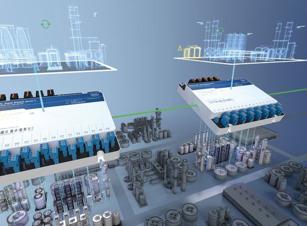
At first glance, the topic of intrinsic safety may seem extremely complicated. It involves observing ignition limit curves, obtaining proof and following specific installation specifications. However, in ongoing operation, users soon find that this seemingly great effort pays off. This means that intrinsically safe circuits can be plugged in or disconnected under load – an advantage that maintenance staff on the production line will appreciate. Nowadays, this type of protection covers a wide range of applications and is currently used in systems ranging from simple point-to-point wiring to digital automation.
Ex i-protected solutions ensure a high level of protection and flexibility
Intrinsic safety enables users to achieve very high levels of safety, allowing corresponding designs to be implemented even in extremely hazardous areas in Zone 0. At the same time, users benefit from outstanding flexibility, particularly when it comes to handling Ex i-protected devices during ongoing operation. This means that extensions and repairs can be performed on live equipment in hazardous areas. Devices can also be added or separated without having to shut down the system or parts of the system. This feature is especially advantageous when troubleshooting or replacing devices.
Further advantages of the intrinsically safe type of protection include the fact that the devices do not require any special enclosure, such as that required by the Ex d (flameproof enclosure) type of protection. Additionally, as a rule, industrial cable bushings and plug connectors are used, which is particularly advantageous when using Ethernet or wireless signals.
Staying under the ignition limit curve
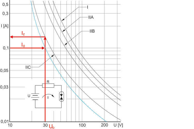
How does it work? The protective principle of intrinsic safety involves limiting the energy in the electrical circuit so that the surrounding explosive atmosphere cannot be ignited by a spark or by impermissible warming of the surface of the electrical components. The typical upper limit for the maximum power in an intrinsically safe circuit is three watts.
The exact pairing of voltage and current is determined using ignition boundary curves. The permissible values must be below the appropriate limit curve. There is a separate curve for each explosion group (IIC, IIB, IIA and I). The maximum permissible values for voltage and current to maintain intrinsic safety are selected by the manufacturer for circuits with linear (ohmic) current limiting on the basis of ignition boundary curves and confirmed by a testing centre.
For use in Zone 1 or Zone 0, the permissible value is reduced by an additional safety factor of 1.5. For example, an intrinsically safe electrical device with a maximum output voltage U0 of 30 V that is to be used in an explosive atmosphere of explosion group IIC may supply a maximum I0 of 102 mA in Zone 1.
One essential aspect of the intrinsic safety type of protection is the question of its reliability when it comes to compliance with voltage and current limits, including when assuming certain errors will occur. Depending on the intended application range (Zone 0, 1 or 2), the letter a, b or c is therefore added to the Ex i device designation. While it is sufficient for these values to be complied with during normal operation for Zone 2, electrical circuits for Zone 1 must be capable of withstanding an error. At the highest level of protection, for use in Zone 0, a device with intrinsically safe circuits must comply with these current and voltage values even if two errors occur.
The same addition also indicates the Equipment Protection Level (EPL) for equipment approved for use in Zone 0, 1 or 2. The EPL, which is written as Ga, Gb or Gc, is indicated in the EC Type Examination Certificate and on the device's type plate.
Verification of intrinsic safety
Intrinsically safe circuits require verification and documentation of their intrinsic safety in accordance with the installation regulations set out in DIN EN 60079-14. In contrast to other types of protection, intrinsic safety must always consider the entire electrical circuit, as well as the combination of current and voltage sources, consumers and connecting cables. Initially, therefore, the output values of the source must be determined and compared with the input parameters of the consumer. The values for maximum voltage, current and power (U0, I0, P0) must be less than or equal to the input parameters of the consumer (Ui, Li, Pi). In a second step, the energy stores – including those of the cable – must be considered, since these could store amounts of energy that could generate ignitable sparks when the circuit is closed or opened. There are also limit values to be considered here.
Since the field devices, such as sensors and actuators, are typically connected to a control room, error events like an overvoltage in the non-hazardous area or a short-circuit current can have an impact on the explosion protection in the plant area. To ensure that the connection between these two areas is safe, a failsafe boundary, for instance a galvanic isolator or Zener barrier, is used.
Keeping users on the safe side
The required values can be found in the operating instructions and the device manufacturer's EU Type Examination Certificate. In the ATEX area, an EU Type Examination Certificate is required for all devices intended for use in Zone 0 or 1, namely the intrinsically safe equipment (generally field devices such as sensors, transmitters and actuators) and the associated equipment (Zener barriers, galvanic isolators or remote I/O equipment). How does this benefit the user? The EU Type Examination ensures that users stay on the safe side, as they can rest easy knowing that the device has been tested and can be used safely.
Exceptions to this rule are simple apparatus such as Pt 100, LEDs, etc., which do not require an EU type examination. However, even in these cases, users must remain vigilant and assess risks, such as the creepage distances and clearances, or electrostatics with regard to enclosures. Furthermore, the inspection of these simple apparatus must be documented. The zone classification, specification of the explosion group, and temperature class are all prerequisites for selecting the right equipment and proving intrinsic safety. Proof of intrinsic safety forms part of the required documentation.
What needs to be considered during installation?
Verification of intrinsic safety ensures that explosion protection is guaranteed – on paper, at least. In practice, in other words during installation and operation, it must be ensured that no external energy sources can render it ineffective. Electromagnetic or electrostatic fields, such as those generated by frequency converters or switching operations, can cause external energy to be fed into intrinsically safe circuits and mean that the limiting values for intrinsic safety are no longer met. The corresponding regulations can be found in IEC EN 60079-14.
Prospects
With the proof of intrinsic safety and the explosion protection document, the user is already on the home straight to safe systems. It is not without reason that the ignition protection type intrinsic safety has played an important role in the automation of process engineering systems for decades. So far, the point-to-point structure with classics such as the 4...20 mA signal has dominated signal transmission. It is also worth taking a look at future technologies that will arise from Industry 4.0/IIoT applications, for example. The use of digital signals such as Ethernet 100BaseT for explosion protection brings intrinsic safety into the future.
What's more, the introduction of Ethernet-APL in process automation is leading to new, exciting tasks. Last year, important tasks relating to standardisation and certification have been completed, meaning that Ethernet-APL is welcoming a new era for intrinsic safety in process automation.
Further Reading:
These articles might also interest you


![[Translate to Englisch:] [Translate to Englisch:]](/fileadmin/user_upload/mitarbeiter/01_DE/07_Blog/00_Allgemein/blog-explosionsschutz-rstahl-startseite-279x205.jpg)
![[Translate to Englisch:] [Translate to Englisch:]](/fileadmin/user_upload/mitarbeiter/01_DE/07_Blog/00_Allgemein/blog-explosionsschutz-rstahl-ueber-den-blog-279x205.jpg)
![[Translate to Englisch:] [Translate to Englisch:]](/fileadmin/user_upload/mitarbeiter/01_DE/07_Blog/00_Allgemein/blog-explosionsschutz-rstahl-autoren-279x205.jpg)
![[Translate to Englisch:] [Translate to Englisch:]](/fileadmin/user_upload/mitarbeiter/01_DE/07_Blog/00_Allgemein/blog-explosionsschutz-rstahl-newsletter-expert-mail-279x205.jpg)
Write new comment